 The flying shears are installed on the rolling line to cut the head and tail of the rolling piece horizontally or cut it to a fixed length. During the movement of the rolling piece, the relative movement of the shearing blade cuts the rolling piece. The schematic diagram of the four-link flying shear mechanism is shown in Figure 1. It consists of upper and lower shearing mechanisms, and the shearing blade is fixed on the connecting rod of the four-bar mechanism. In a practical flying shear mechanism, the driving force is input from the lower crank. A pair of helical gears with the same number of teeth drives the upper crank to move at the same rotational speed, and the mechanism cuts the workpiece once for each revolution of the crank. In order to simplify the structure and facilitate the measurement of shear force, the same magnitude of moment is added to the two cranks in Figure 1 to reduce the modeling of the helical gear.
 Curved Arm Flying Shear
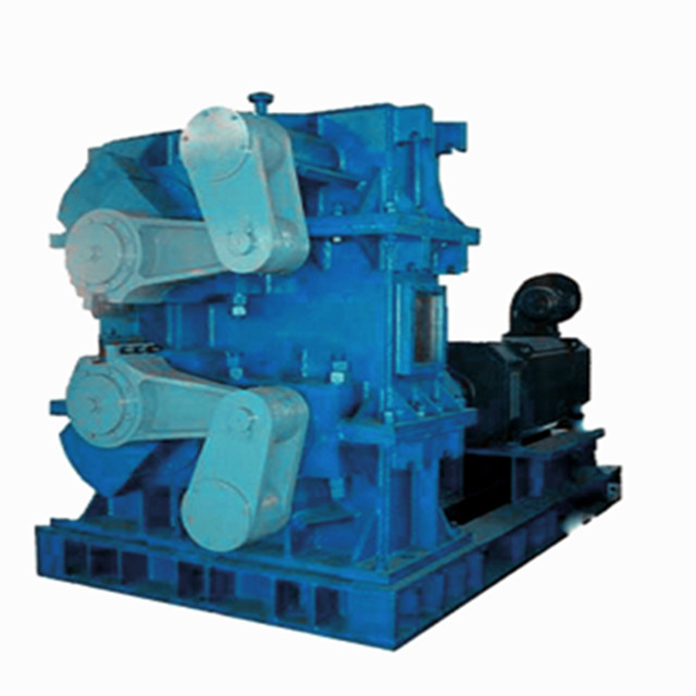
The shearing machine for rolling pieces in transverse shearing operation is called flying shear. It is a processing equipment that can quickly cut iron plates, steel pipes and paper rolls. The product in rolling bar shearing has the characteristics of low power consumption and low investment cost.
Products Details
The flying shears are installed on the rolling line to cut the head and tail of the rolling piece horizontally or cut it to a fixed length. During the movement of the rolling piece, the relative movement of the shearing blade cuts the rolling piece. The schematic diagram of the four-link flying shear mechanism is shown in Figure 1. It consists of upper and lower shearing mechanisms, and the shearing blade is fixed on the connecting rod of the four-bar mechanism. In a practical flying shear mechanism, the driving force is input from the lower crank. A pair of helical gears with the same number of teeth drives the upper crank to move at the same rotational speed, and the mechanism cuts the workpiece once for each revolution of the crank. In order to simplify the structure and facilitate the measurement of shear force, the same magnitude of moment is added to the two cranks in Figure 1 to reduce the modeling of the helical gear. Featured Products
-
Industrial Gear Speed Reducer
-
Roller Mill Forging Steel
-
Thin Plate Rolling Mill For Industrial Production
-
Induction Melting Furnace Smelting Equipment
-
Continuous Casting Machine Crystallizer Assembly
-
Crank flying shear
-
Industrial Aluminum Plate Rolling Mill
-
Continuous rolling mill(High stiffness)
-
Vertical mill
-
Industrial Steel Rolling Mills
Contact us
Please feel free to give your inquiry in the form below We will reply you in 24 hours